Tuesday, August 20, 2013

Blob Analysis

Sometimes, we would like to get measurements from images and the process would be easier if the region of interest (ROI) is clearly distinguishable from the rest of the image. In other words, we want our ROI to be well-segmented from its background and it can be achieved by edge detection or by specifying the ROI as a blob. Either way, the images must be first undergo preprocessing in order to make them more suitable for performing the desirable measurements. This activity makes use of blobs to analyze the 'cells' found in the image.


Determining the best estimate of area of the cells

In image processing, blob is considered to be a region of connected pixels. In Scilab, blobs are detected from binary images which exclude them to the background pixels or those having zero values. You can see below the image of white circles which we consider the cells


To process the images easier and faster, it was cropped into 256x256 pixels subimages. The image was cropped using GIMP and we allowed overlapping subimages. This resulted to 12 subimages.


One subimage (upper left part of the whole image) is shown below.

Subimage 1.

To segment our regions of interest, we need to binarize the image. We have to consider the histogram of the image in order to determine the enough threshold value to produce an output image that will best isolate our cells and background. I first used the usual imhist() function and obtain its peak for the threshold but it was tiring and time consuming given that we have 12 subimages. So it was grateful to know that Scilab has all its way of making our image processing easier :). As I explored the Image Processing Design (IPD) module of Scilab, I came across the CalculateOtsuThreshold() and SegmentByThreshold() functions. (IPD is available on ATOMS Module Manager of Scilab. You would only need to install it manually.) The first function is able to solve the threshold of the images automatically while the latter is used to binarized the image with the set threshold value

We favor the values higher than the threshold to clearly represent the cells, just don't make it so high that everything would appear black. So in binarizing the image, we add 20 to the calculated threshold value. This resulted to more distinguishable ROI and background. The comparison of using different threshold values can be seen below.


Converting the image to its binary image with threshold equal to the image threshold value (left) and threshold+20 (right).

Seen below are all the binarized subimages


However, this image cannot still be used for measurement analysis because this is still 'dirty'. With the use of morphological operation done in the previous activity, the image can be further cleaned up. Understanding the closing, opening and tophat operator, the image can be cleaned nicely. I really had a hard time doing this part because there were a lot of factors to consider. First, was the structuring element to be used then you would then think of the right combination. I understand well the use of the closing and opening operator because its name was already self-explanatory, while the tophat operator is just confusing. So I decided not to use it in this activity :P

A sample of the cleaned image applying closing operator first (left) then open operator (right).


I realized that the structuring element that I need to use was a circle, the same shape as our cells. The only problem is the size. I first use the CloseImage() function so that our ROI will fully cover our cells then OpenImage() function was used to separate adjacent cells. This separation was only effective for cells nearly touching each other but for overlapping cells, it just doesn't do much. However, this operator was still useful because this make the excess dirt pixels in the background to be wiped out. See image above :)

Shown below are all the cleaned subimages.


Now, we can now analyze our blobs. SearchBlobs(), another function of IPD, was used to assign numbers to each blob found in the image. Now, each blob can be called separately, thus will able to analyze its features like area.To ensure that the blobs have their own individuality, the ShowImage() function was used resulting to the graph of blobs respresented with different color. And just for the heck of trying, I tried the the bounding box feature, which can all be found in the blob analysis in the IPD module.


The area of each blob can be easily computed using the size or the length function however, the area of each cell cannot be obtained because not all the blobs represent only one cell as what is observed on the blobs on the right portion of the images above. So I establish a code that if it consider the the blob contains two cell, the area will be divided by two, and so on. I completely understand that this procedure will make the estimate inaccurate but this was the best solution that I could think of.

Table below shows the area computed for each blob of each subimages.


From all these data the computed mean and standard deviation were 525.69605  and 94.437235, respectively. The calculated best estimate of the area of the 'cells' is


Isolating the cancer cells from the healthy ones

Using the best estimate, the cancer cells, represent by abnormally large size cells, can be isolated from the normal cells. The image containing both cancer and normal cells is shown below.


Doing the same process in first image, we search for the blobs in this second image. I just processed the image as it is, without any cropping. The binarized image and the cleaned image are shown below


I isolated the cancer cell simply by using the FilterBySize() function of the Scilab with bounds of [431, 620] repesenting the range of the best estimate of the area. The result is as follows.


This looks pretty much right. The cancer cells were removed however other normal cells were also removed. The cells that was taken out was displayed by setting the parameters of FilterBySize() greater than the best estimate bounds.


So, yes! There were normal cell that be removed. The same as the problem previously, there were overlapped cells and since they were big, the code consider it as cancer cell.

I give myself a grade of 10/10. I wasn't able to produce the desired output but I give myself a consolation point for exploring other stuff and the product of real hardwork :)

__________
References
[1] Soriano, M. "Application of Binary Operations 1 : Blob Analysis." AP 186 Laboratory Manual. National Institute of Physics, University of the Philippines, Diliman. 2013.


This been an exhaustingly dull weekend and weekdays. The rain just really set the mood a little off. I've been confined inside my room for like countless days, sitting in front of my computer doing my blogs and papers, or listening to music, or watching TV, and just going outside in need for food. And whenever I see bad news concerning the storm, I can't help but feel down.. especially if the news is about your province. Bataan is now under state of calamity and all I can is pray for the safety of my friends and loved ones. Stay safe everyone!

Morphological Operations

Morphology refers to the study of shapes, forms and structures. Classically, morphological operations are done on binarized images. By applying different morphological operations, the images were modified. The were a lot of possible outcome on the image, may be narrowed, widened, hole may be filled or connected blobs may be separated.

Some of the morphological operations were erosion and dilation.

Erosion operator is defined by

The product of the erosion is to reduce the image A by the shape of B. The image should obviously be narrower or thinner.

Dilation operator is defined by

The product of the dilation is to expand the image A by the shape of B. The image should obviously be thicker or wider.

The images to be applied with morphological operations are as follows:

  1. A 5×5 square
  2. A triangle, base=4 boxes, height=3 boxes
  3. A hollow 10×10 square, 2 boxes thick
  4. A plus sign, one box thick, 5 boxes along each line


The structuring elements to be used, on the other hand, were the following

  1. 2×2 ones
  2. 2×1 ones
  3. 1×2 ones
  4. cross, 3 pixels long, one pixel thick
  5. A diagonal line, two boxes long


Erosion and Dilation results

The set of erosion and dilation results includes the one done by hand (graphing paper images) and the other using Scilab functions.

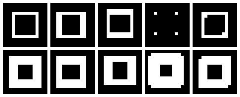
Erosion and dilation of a 5×5 square by the set of structuring elements


Erosion and dilation of a triangle, base=4 boxes, height=3 boxes by the set of structuring elements


Erosion and dilation of a hollow 10×10 square, 2 boxes thick by the set of structuring elements


Erosion and dilation of a plus sign, one box thick, 5 boxes along each line by the set of structuring elements


The predicted result were all matched with the code-simulated result. With this I give myself a grade of 10/10 by accomplishing all the required output.

________________________
[1] Soriano, M. "Morphological Operations." AP 186 Laboratory Manual. National Institute of Physics, University of the Philippines, Diliman. 2013.

Color Picker

In an image, an object or a portion can be segmented from the rest of the image by considering its color. From the image below, the green cap was the one to be segmented. 


The Region of Interest (ROI) that was picked from the image is shown below


Using Scilab, the red, green and blue channel or component of the image is separated. The raw RGB values were transformed to its normalized chromaticity coordinates (NCC) using the equations below

where I = R+G+B is the intensity value of the color.


Parametric Probability Distribution Estimation

Each pixel of the ROI has its rgb chromaticity values. This segmentation makes use of the mean and standard deviation of the rgb chromaticity values of the ROI. The probability of each image pixel with chromaticity r that belongs to the color distribution of the ROI is defined by

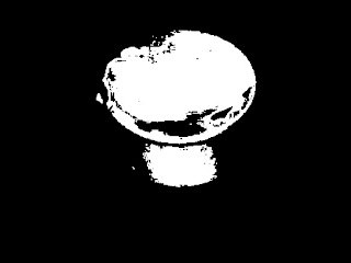
similar equation is done for the probability having chromaticity g.The joint probability results to the final segmented image, which for our image is shown below. 


Non-parametric Probability Distribution Estimation

Non-parametric segmentation is done by getting the value of each pixel of the ROI. The values were plotted in the 2D histogram. A certain color has its certain location in the NCC color space. The 2D histogram of our ROI is represented below. The white patch in the histogram was observed to agree with the desired location of the green in the NCC space. 


The 2D histogram was used to backproject the values to the whole image. The value of each pixel of the image were located in the histogram and whatever the values in that location will be the value replaced in that pixel. The result of the non-parametric color segmentation is as follows. 


For both of the color segmentation, however, not the entire cap was segmented. The portion that was not segmented were the darker shades of green. Making the ROI cover a bigger area to better represent the color, especially those of lower brightness, the figure below shows the new ROI and its corresponding 2D histogram. 


The output of the parametric and non-parametric color image segmentation is as follows. It was observed that when the ROI is made bigger, which better represents the all the shades of color of a region, the segmentation is improved. 

Output of parametric (left) and non-parametric (right) color image segmentation


Let's try for other picture :)


I try to isolate each color..

This technique really have amazing results. The upper set is the parametric while the lower set is the non-parametric color image segmentation.


In my outputs, it was observed that non-parametric segmentation better and cleaner segmentation. Also, it is faster since no computations of mean, standard deviation and probabilities were need to do the segmentation. 

I give myself a 11/10 for accomplishing the desired result. Additional points for trying to make the ROI bigger and applying the segmentation is many other objects. 

________________________
[1] Soriano, M. "Color Image Segmentation." AP 186 Laboratory Manual. National Institute of Physics, University of the Philippines, Diliman. 2013.


Sunday, August 11, 2013

Enhancement using Fourier transform

Some images contain unwanted repetitive patterns like lines. Well, this was never a problem for our experts in image processing. These unwanted patterns can be removed by masking or covering the frequencies seen in their Fourier domain.[1] This activity discusses how it can be done.

To know the desired filter mask to remove the repetitive pattern, we must understand first the convolution theorem.[1] For that, what we can do first is to observe the FFT of different repetitive patterns and convolution of some images.


Pair of dots and other pair-figures along the x-axis

First, we were asked to create binary image of two one-pixel-dots symmetric about the center along the x-axis. The FFT of this image as shown below consists of alternate black and white vertical lines.

Binary of two dots symmetric along the x-axis (left) and the FFT of that image (right). 

The dots were replaced by circles of different radius. Just like the FFT of only one circle, as the radius of the circle is increased the pattern observed on its FFT become smaller. In addition, black and white vertical patterns were also observed on their FFTs. As you scroll down, same thing happen for other images like two squares and two Gaussian circles. 

Images of two circles of different radius and their corresponding FFTs.

Images of two squares of different length and their corresponding FFTs.

Images of two Gaussian circles of different sigma and their corresponding FFTs.


How about patterns along the y-axis?

What if the figures/patterns were along the y-axis? We could infer that instead of vertical black-and-white patterns, their FFT would have patterns along the horizontal. To confirm our guess, we get the FFTs of images with patterns along the y-axis as shown below.

So, our guess was right!


Convolution with image having Dirac deltas in random position

Image with dimension of 200x200 pixel containing ten 1’s or white dots placed in random locations was created. The dots will approximate Dirac deltas[1]. Another image of same dimension with any 5x5 pixel pattern on its center was created.

5x5 pattern

The two images were convolved and the resulting image is presented below. We can observe that in convolution output image, the pattern took up the Dirac delta positions. This result is just what is expected considering the convolution theorem.

Image of pattern, image with 10 random Dirac delta locations and the convolution output. 


Horizontal and vertical patterns

Horizontal and vertical repetitive patterns were created by making equally spaced 1’s along the x- and/or y-axis. For vertical or horizontal patterns, the FT is shown below. It can be observe that when the image has horizontal patterns, most of the information of its FFT was found along the x=0 axis. While the image with vertical patterns has most of the information of its FFT along the y=0 axis.

Images with vertical (up) and horizontal (down) patterns with their corresponding FFTs. 

For combined vertical and horizontal pattern with different spacing, the FT results to the following. As the spacing is decreased, the spots in the FFT pattern lessens. Or in other way of observing it, as the pattern in the real space decreases, the pattern in the frequency space increases.

Horizontal and vertical lines of different spacing and their corresponding FFTs. 


Lunar landing scanned pictures: Line removal

In some images, we encounter some unwanted lines. We were given an image captured outside our planet described as "Lunar Orbiter image of one of the craters in the far side of the moon". It contains some unpleasant horizontal lines and we would like to remove those. Since we have known where the information of the horizontal lines in the Fourier domain, the mask that should apply will be that could cover it (white line along the vertical). The filtering was illustrated in the figure below.

FFT of the image (left) and masked FTT (right). 

The original and the resulting image are as follows:

How cool was that? Lines was no longer seen on the processed image :)


Oil on canvas: Weave modelling and removal

We have another test subject seen below - the detail of Frederiksborg, oil on canvas by Dr. Vincent Daria. The image contains weave patterns and we must put some filter mask to remove these unwanted patterns on the painting. 


The image was first read as grayscale and the FFT of the image was shown below. Unlike other FFTs, this contain bright dots scattered around with somekind of arrangement. 

FFT of the Frederiksborg detail. 

It is known that most of the information about the image was located at the center of its FFT.[2] So we thought of making a mask that will cover most of the FFT leaving only significant portion at the center. The mask will not just cover unnecessary information about the image, but will also be easy to apply to the FFT. 

First filter mask (left) and the masked FFT (right). 

However, we are also asked to get the inverse FFT of the filter mask, but it just won't give us anything. So, another filter mask, containing dots that will only cover the bright white dots of the FFT, was used. 

Second filter mask (left) and the masked FFT (right).

The color of the second mask was inverted and when the inverse FFT of it was obtained, the output look something like the weave pattern. Huh, interesting! :)

Inverse FFT of the second mask (left) with its zoomed in version (right). 

The image of the painting in grayscale is shown below.


Now applying the filter masks...

Resulting grayscale image applying the first filter mask (top) and second filter mask (bottom). 

I think it was really a good idea to use the second mask because it resulted to better enhanced image. Both are able to remove the weave pattern but the second was not that blurry compared to the first. Maybe because there been much information lost when the first mask was used. 

Hmm.. Recently, I realized that my data has been so dull, they contain no color at all.. Luckily, I have learned to manipulate image colors using Scilab... 

TADAH! 

Resulting image applying the first filter mask (top) and second filter mask (bottom). 

I really like the result of using the second filter :) 

For this activity, I thank Joshua for all the help on debugging my code. For the knowledge on how to use Scilab in managing the color channels of the image, I would like to thank Floyd. 

I would give myself a 11/10 for this activity for accomplishing all the goal. A bonus of 1 point for doing the last part in colors. 
__________
References
[1] Soriano, M. "Enhancement in the Frequency Domain." AP 186 Laboratory Manual. National Institute of Physics, University of the Philippines, Diliman. 2013. 
[2] R. Fisher, et al. Fourier transform. Retrieved from http://homepages.inf.ed.ac.uk/rbf/HIPR2/fourier.htm